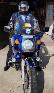
I've been getting my '75 R90/6 finished up and had an issue come up that I'm not sure about. I've been pretty careful about making notes and taking pictures, but missed it all on the horns. The bike came w/ a pair of Fiamm horns and a Fiamm relay. The installation was pretty bodged up and there was no way I was going to put it back together the way it was. I've made a new, solid mount for the horns and the relay is now under the tank, below the brake MC. My issue now is with wiring up the relay: It's an older model w/ three terminals and a ground wire. The terminals are labeled (factory stamped) H B S. Based on what I've found on the internet H = Horn, B = Battery, and S = Switch. The wires from the horns go to the H terminal, no question there. The diagrams I've found on the internet show the B terminal wired directly to the battery and the wire from the switch goes to the S. When it came to me the two BMW horn wires were connected to the B and S terminals. The problem is that I'm not sure which wire to put on which terminal. I'm thinking that the + from the switch should go to B and the other wire (which is a ground) should go to the S. Can someone confirm this for me?
Thanx!
If you like our site, please consider joining our club!
By joining you will help ensure that we can continue to provide this service
JOIN HERE!
By joining you will help ensure that we can continue to provide this service
JOIN HERE!
Fiamm horn/relay question.
-
schrader7032

- Posts: 9058
- Joined: Fri Oct 27, 2006 3:00 am
- Location: San Antonio, TX
- Has thanked: 3 times
- Been thanked: 36 times
Re: Fiamm horn/relay question.
Not sure I'm aware of a factory relay with HBS stamped on it. Should be part number 61 31 1 373 585 with 4 pins. The handlebar inputs would be across pins 85 and 86, and power from the battery goes to pin 30 and output to the horns is pin 87.
You can test what you have using your logic. If you think S means switch, put 12v across those two pins. Measure the continuity across the other two pins. Before applying the 12v, the resistance across the other two pins should be infinite. Once the 12v is applied, the resistance should go to 0. If that's the way your switch work, then you have probably figured out what HBS means.
You can test what you have using your logic. If you think S means switch, put 12v across those two pins. Measure the continuity across the other two pins. Before applying the 12v, the resistance across the other two pins should be infinite. Once the 12v is applied, the resistance should go to 0. If that's the way your switch work, then you have probably figured out what HBS means.
Kurt in S.A.
'78 R100/7 '69 R69S '52 R25/2
Fast. Neat. Average. Friendly. Good. Good.
'78 R100/7 '69 R69S '52 R25/2
Fast. Neat. Average. Friendly. Good. Good.
-
srankin
- Posts: 1085
- Joined: Fri Jul 14, 2017 8:45 pm
- Location: Spencerport, NY USA
- Been thanked: 21 times
Re: Fiamm horn/relay question.
As Kurt writes, I believe (and sorry I haven't looked at a wiring diagram yet) he covers the pins and connections in the headlight shell and stock harness.
Stock horns on BMW bikes don't draw a lot of current, in most of the single horn bikes there is not even a relay installed. To be honest I haven't looked at a /6 wiring diagram yet and I would not be surprised if there was not a relay for even dual stock horns.
Relays are installed to provide high current to high current using objects while being controlled by a low current switch. You don't want a heavy gauge wire in your switch but, you might want it for the item.
If BMW felt the current flow to the horns was low enough, they may not have used a relay for the horns. As I write I haven't looked at a diagram so I don't know for sure.
The two wires down by where the horns/horn mounted are the stock horn hot wires. One wire would be for left and one for right IF they are the same color wire. If the wires are colored anything other than brown, a colored wire other brown, it is a hot wire. Brown on BMW is ground. So if both wires are colored, you could safely hook your horns to them PROVIDED the horns you are installing are similar to BMW stock horns. Air horns are out, LOL.
If there are two wires there, hook up your horns.
I hope I haven't confused you. I will try to get to the shop this morning and look to see what is what in wiring diagrams.St.
Owner of a 84, R80RT and 78, R100RS
-
srankin
- Posts: 1085
- Joined: Fri Jul 14, 2017 8:45 pm
- Location: Spencerport, NY USA
- Been thanked: 21 times
Re: Fiamm horn/relay question.
So, I got my lazy butt out to the shop and looked up your bike. According to the wiring diagram, you had one horn for the bike. There was NO relay in the system. Power was a green black wire. The horn was switched or operated by grounding it out via the horn button. This was the brown with white stripe wire at the horn. on the other side of the switch was a brown ground.
What you had in effect defeated the purpose of the relay, the previous owner had no idea how a relay was supposed to work nor how to add a relay into the stock wiring.
I don't know quite yet how I would wire the relay you have on hand which as Kurt points out is not stock. The stock four pin relay would have a wire (green Black most likely) operating the relay as a hot side and this would be grounded by the switch. This would be the low current draw circuit with green black as a hot and a ground controlled by a ground at the switch.
This would cover two of the four terminals. The other two terminals would be either one wire for the left horn and one for the right or power for the horns back to ground, the higher current side.
In your case the green black wire is hot all the time. The brown white wire is switched. I don't see a wire you can tie into to properly wire the three pin relay you have.
Give me some time and perhaps I can figure something out, St.
Owner of a 84, R80RT and 78, R100RS
-
srankin
- Posts: 1085
- Joined: Fri Jul 14, 2017 8:45 pm
- Location: Spencerport, NY USA
- Been thanked: 21 times
Re: Fiamm horn/relay question.
So FYI, here is the stock wiring for your one horn bike and for comparison a two horn bike.
As you can see in the two horn system there are two complete circuits, one for switching and one for power. St.
As you can see in the two horn system there are two complete circuits, one for switching and one for power. St.
- Attachments
-
-
Owner of a 84, R80RT and 78, R100RS
-
RideSolo

- Posts: 52
- Joined: Tue Dec 12, 2023 6:14 pm
- Location: Bucyrus, OH
- Has thanked: 13 times
- Been thanked: 4 times
Re: Fiamm horn/relay question.
Thank you all for the comments. I'm sure this bike had a single horn from the factory. The mount on the frame is there as well the stock pair of horn wires. Somewhere along the way somebody, I suspect the original owner, put on these Fiamm horns and a Fiamm relay. The installation was pretty sketchy w/ a couple of 1/4" thick aluminum bars bent to shape and the wiring was even worse; bodged connectors w/ ugly balls of half-sticking electrical tape. What I didn't pay attention to when I took that all off was which wire went where. (Since then I've been more careful w/ notes, pictures, labeled zip-lock bags, etc.)
This is a good diagram I found:
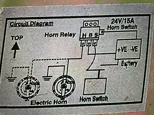
I'm thinking that the + horn wire ought to go to the B and the - wire should go to the S but I'm not sure. Guess what I can do is just try it and see what happens.
This is a good diagram I found:
I'm thinking that the + horn wire ought to go to the B and the - wire should go to the S but I'm not sure. Guess what I can do is just try it and see what happens.
'75 BMW R90/6 "Rocinante"
Cory E.
Bucyrus, Ohio
Retired USAF
Cory E.
Bucyrus, Ohio
Retired USAF
-
schrader7032
- Posts: 9058
- Joined: Fri Oct 27, 2006 3:00 am
- Location: San Antonio, TX
- Has thanked: 3 times
- Been thanked: 36 times
Re: Fiamm horn/relay question.
Pretty confusing. Two switches? Or is the "24V/15A" upper right just saying what the switch type is?
Kurt in S.A.
'78 R100/7 '69 R69S '52 R25/2
Fast. Neat. Average. Friendly. Good. Good.
'78 R100/7 '69 R69S '52 R25/2
Fast. Neat. Average. Friendly. Good. Good.
-
srankin
- Posts: 1085
- Joined: Fri Jul 14, 2017 8:45 pm
- Location: Spencerport, NY USA
- Been thanked: 21 times
Re: Fiamm horn/relay question.
The diagram you have shows a "hot" switch, the factory version is shown in the bottom diagram I posted. In this case there are two separate wiring routes, one for the switch with a hot and ground and one for the horns with a hot and ground.
The confusion is the horn diagram you have shows the Switch is grounded along with the horns at a common point, the terminal on the side of the relay, so there are not two switches just a poorly worded diagram.
This diagram is also showing incoming power is via only one point at the B terminal on your relay for both the switch and horns.
Sorry for something so simple I am having a hard time wrapping my head around the aftermarket relay, and what wires in the factory system to tie into.
LOL, the factory two horn system throws in a clinker with the black and green hot wire going to the switch.
Still thinking, St.
Owner of a 84, R80RT and 78, R100RS
-
schrader7032
- Posts: 9058
- Joined: Fri Oct 27, 2006 3:00 am
- Location: San Antonio, TX
- Has thanked: 3 times
- Been thanked: 36 times
Re: Fiamm horn/relay question.
This is a diagram from the BMW Electrical CD. I'm showing the twin horn schematic for the R100/7...my /7 came to ne with the Fiamm horns installed.
- Attachments
-
Kurt in S.A.
'78 R100/7 '69 R69S '52 R25/2
Fast. Neat. Average. Friendly. Good. Good.
'78 R100/7 '69 R69S '52 R25/2
Fast. Neat. Average. Friendly. Good. Good.
-
srankin
- Posts: 1085
- Joined: Fri Jul 14, 2017 8:45 pm
- Location: Spencerport, NY USA
- Been thanked: 21 times
Re: Fiamm horn/relay question.
Kurt, that is the same schematic as the color one I provided. LOL, The problem is, there are two vastly different systems between the single horn /6 and the dual horn /7.
The single horn system had the horn as "hot" all the time via the green black wire and to operate it was grounded via the switch via the brown white wire at the horn on one side of the switch to a ground or brown wire on the other side of the switch.
The factory two horn system uses a hot green black wire on one side of the button and a ground on the other side to fire the relay to provide a circuit for the horns. This button has a hot side all the time, unlike the single horn bike where the horn itself is hot all the time.
I maybe over thinking the issue but, as I see it, there is no power flowing through his button. I am trying to think of a neat tidy way to utilize the stock BMW wiring as much as possible. Forgive me, I can't find a way yet.
Most aftermarket relays are installed with direct wires to the battery for the high current side. The blog of wires the previous owner installed most likely had this. And, it may have to be done again like that albeit neater.
With the OM relay, I see a common ground for the button and the horns. So I can't or don't see a way for the button to control the ground on the low current side. It looks to me as if the relay is set up to have power flowing through the button. This means the button would have to be rewired to have a hot side and a ground side like the 2 horn factory system.
I personally don't like rewiring things from factory. Anyway, maybe it will all become clear or something will be figured out.
Sorry, St.
Owner of a 84, R80RT and 78, R100RS