I own a 1976 R90/6 that I love. Fully restored it myself. However, my problem is with my father's 1971 R75/5. At the end of the summer when he went to ride it, after turning on the key smoke started pouring out of the headlight bucket. He turned it off, no flames (thank goodness), and disconnected the battery. Now, it's in my garage to fix.
So, I opened the headlight, and as you might expect, there were a lot of melted wires. Most were melted together. I documented it as best I could with photos, but it wasn't a pretty sight. It looks like the worst came from the common ground wire connecting the idiot lights; however, it also went up into the right handlebar switch.
I replaced both handlebar switches from MAXBMW (love that place!). I also had to remove the ignition and light switch (those tabs are frightening!). So, as I'm looking at the switch, things are fairly straightforward except for one mystery wire. I can't find it documented ANYWHERE; however, I've seen it in online pictures... just no mention of what it goes to... and, it's in several different color configurations. On mine it's green, but I've seen it as white and white/black.
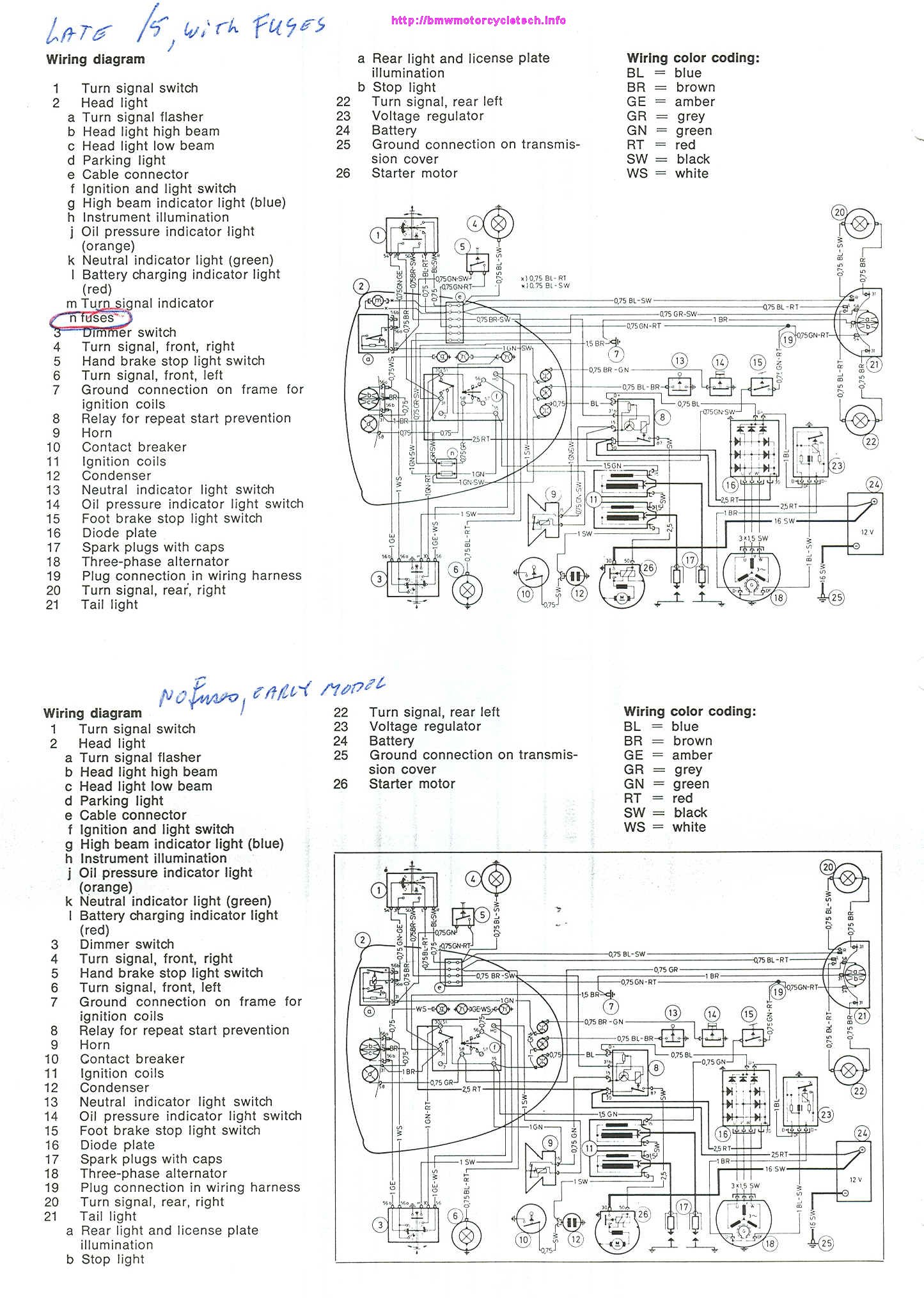
The actual wiring diagram from the original owner's manual shows that there are no white or white/black wires attaching to the ignition and light switch. Also, the only green wires I see illustrated all come from post 15, and include the common ground for the idiot lights (to flasher relay post 31), one going to the right ignition coil, and one going to the horn (post 15). Yet, I have this unidentified green wire, soldered to the switch, which is energized when the key is in the on position. It's looking kind of ragged, and I'll replace it... just need to know where the other end goes! Haha.
And, yes, I am labelling every wire with shrink wrap. I find that makes my life much easier down the road. I've attached 2 pics showing both sides of the switch. In both pics I have circled the connection spot in green and used an arrow to point to the wire. Any help would be greatly appreciated!!
Also, if there's any interest, I've got a spreadsheet (saved as a .pdf) that shows every wire and where it goes on this R75/5, including color and size. I'll gladly share it, if told where you'd like me to post it.
If you like our site, please consider joining our club!
By joining you will help ensure that we can continue to provide this service
JOIN HERE!
By joining you will help ensure that we can continue to provide this service
JOIN HERE!
R75/5 Ignition Switch - Mystery Wire
R75/5 Ignition Switch - Mystery Wire
- Attachments
-
- img_0787_1.jpg (5.62 MiB) Viewed 6892 times
-
- img_0786_1.jpg (5.67 MiB) Viewed 6892 times
-
schrader7032

- Posts: 9062
- Joined: Fri Oct 27, 2006 3:00 am
- Location: San Antonio, TX
- Has thanked: 3 times
- Been thanked: 36 times
Dr. B - Welcome! I saw your
Dr. B -
Welcome! I saw your post on the MOA forum...kind of forgot about it some. I've looked in my Haynes and the 30/51 post on the ignition switch board shows two wires attached to it. One solid red, fairly thick, going to terminal 30 on the starter relay. Another green wire with red stripes goes to terminal 30 on the lights/horn switch. As I recall, red wires are hot all the time, while green wires with red stripes are switched power.
Do you have anything currently going to that terminal on the horn switch? Maybe someone replaced the original green/red wire with solid green at some point.
Kurt in S.A.
'78 R100/7 '69 R69S '52 R25/2
Fast. Neat. Average. Friendly. Good. Good.
'78 R100/7 '69 R69S '52 R25/2
Fast. Neat. Average. Friendly. Good. Good.
No, this wire isn't connected
No, this wire isn't connected to any terminal. It's actually soldered to the board, at the end that would be contacted if the key were turned clockwise. I'm at a loss. There have been modifications made to this bike before my Dad bought it; however, it was running prior to the smoking incident. Below you can see the pictures of the wire... hoping they're clear.
in the first image, I've circled where the wire is soldered, so you can see it in relationship to the board. In the second image, you can see the proximity to terminals, but it is soldered. Any help is appreciated.
in the first image, I've circled where the wire is soldered, so you can see it in relationship to the board. In the second image, you can see the proximity to terminals, but it is soldered. Any help is appreciated.
- Attachments
-
- img_0787_1.jpg (5.62 MiB) Viewed 6892 times
-
- img_0786_1.jpg (5.67 MiB) Viewed 6892 times

That isnt a very good clean
That isnt a very good clean solder to 30/50 (51?). I would say that wire has been replaced sometime in its life. Does your wire diagram show where the wire would go no matter what color it is?
twocams
twocams
Twocams
92 R100RT/69 R69S
2004 Aprilia Atlantic 500cc single cylinder Scooter
83 Honda V65 Magna, fastest production bike in1983
2015 Can Am Spider SE6 1,688 miles
2018 Moto Guzzi V711 Special
92 R100RT/69 R69S
2004 Aprilia Atlantic 500cc single cylinder Scooter
83 Honda V65 Magna, fastest production bike in1983
2015 Can Am Spider SE6 1,688 miles
2018 Moto Guzzi V711 Special

not white (WS) but gray (GR)
I have four boards on hand and on each of them, that wire in question has gray insulation.

the wiring diagram shows it from position 58, powering instrument illumination and parking lights.
The green wire at upper right on my board shown above runs power to the idiot lights (oil press, gen & neutral) horn, turn signal flasher relay, etc.
Two of my switch boards don't have the fuse holders - being from early /5s - otherwise they all look the same.
Have you looked at DIN 72552? https://en.wikipedia.org/wiki/DIN_72552
it indicates #58 is for "licence plate lights, instrument panel". Scroll down to Lights for that. I believe the DIN has been revised since '71, but usually all the little numbers near electrical connections describe the function through the DIN coding.
I'm interested in seeing your wiring spreadsheet. I'm assembling a '71 and the harness is just about next.
'61 R27, '63 R60/2 etc.
-
Snakecharmer

- Posts: 7
- Joined: Sat Jan 20, 2018 1:44 pm
Headlamp wiring
Hello, IO too am about to attempt to wire my 1971 R75/5 and would appreciate a copy of your pdf wiring info please? I have been dreading this part of the process ever since strip down and need all the help I can muster.
Anyone got any information on how to assemble the headlamp switch itself?
Regards, in anticipation.
Anyone got any information on how to assemble the headlamp switch itself?
Regards, in anticipation.
- Attachments
-
- dscf6443.jpg (975.22 KiB) Viewed 6892 times
Give a child a hammer and it thinks the whole world is a nail!

Headlight wiring..
And when you rotate the key clockwise (parking light position) you have nothing but a taillight and a parking light in headlight on (the way this is wired) correct?
Re: R75/5 Ignition Switch - Mystery Wire
Drbillk - if you have the pdf wiring diagram for the R75/5 still available that would be most helpful as my ignition switch has broken and the diagram I have is not very easy to read or magnify to a larger size. Thanks
-
r67boxer
- Posts: 77
- Joined: Tue Jun 28, 2022 8:04 pm
- Location: Pender Island, Canada
- Been thanked: 6 times
-
schrader7032
- Posts: 9062
- Joined: Fri Oct 27, 2006 3:00 am
- Location: San Antonio, TX
- Has thanked: 3 times
- Been thanked: 36 times
Re: R75/5 Ignition Switch - Mystery Wire
Snowbum has diagrams on his website:
https://bmwmotorcycletech.info/1973-electricals.pdf
https://bmwmotorcycletech.info/Slash5Schematic.jpg
Snowbum's website is available through the Knowledge Base link in the upper right.
https://bmwmotorcycletech.info/1973-electricals.pdf
https://bmwmotorcycletech.info/Slash5Schematic.jpg
Snowbum's website is available through the Knowledge Base link in the upper right.
Kurt in S.A.
'78 R100/7 '69 R69S '52 R25/2
Fast. Neat. Average. Friendly. Good. Good.
'78 R100/7 '69 R69S '52 R25/2
Fast. Neat. Average. Friendly. Good. Good.