To me, if the idea was to cool the compressed fuel/air mix, I would have put finned collars on the intake tube (that is in the air stream) between the compressor and the head.
While it may cool the fuel/air mix a bit, I think the primary intended purpose of finned nut is to reduce the head temp around the intake valve.
The end result is, I suppose, that if you cool one (head at intake valve), it will alos provide some cooling to the other (fuel air mix).
It would be interesting to know how well it actually worked.
Has anyone read how much boost the superchargers created?
Best regards,
Bruce
If you like our site, please consider joining our club!
By joining you will help ensure that we can continue to provide this service
JOIN HERE!
By joining you will help ensure that we can continue to provide this service
JOIN HERE!
Type 255 Kompressor
-
bmwmyplace
- Posts: 149
- Joined: Mon Feb 26, 2007 6:23 am
Type 255 Kompressor
I think you will find the finned nuts are simply for decoration and have nothing to do with the performace of the machine.
If you look at the BMW archives you will probably not find one with fins on it ....typial of some restorers , they put a personal touch to their work, and nothing more PG
If you look at the BMW archives you will probably not find one with fins on it ....typial of some restorers , they put a personal touch to their work, and nothing more PG
Type 255 Kompressor
the reason for intercoolers in forced fed applications is to reduce the thermal gain the mixture (for a suck thru application) or air (for a blow thru) experiences while being churned about in the compressor
however, they do drop pressure although hopefully a tolerable amount
certainly more pronounced in turbo applications but the most efficient mechanical blowers weren't available back then
I think they are the teflon tipped screw types and the Germans didn't patent them until the 60's....... and I am pretty sure that particular patent did not include teflon tips as they didn't seem to come about until later
probably due to materials availability and the difficulty in machining a precision dovetail on a helix to accept the tip
making, starting with only a notion, a three lobed screw pair today along with machining it to run teflon at very tight clearances...... it really affordable and doable
so my opinion is anything one can do to dissipate heat from the intake charge and engine........ with better being to minimize heat transfer into the engine.. and use it in making the piston going DOWN and then exit the the exhaust
is a good thing but for forced fed applications....... some form of inertial/adiabatic/intercooling does minimize both thermal and mechanical losses involved with the process
for the bmw the toss up is do you turn the heads around and have to deal with directing airflow to the exhaust....... probably worth it for a blown application but my guess is that only salt flats type comparison runs would tell the tale
my opinion of the cooling fins for a blown app is that the whole intake tract would benefit and just one tiny clamp at the head is likely just candy
and yes the runners should be brightly polished or chromed externally
-
Bruce Frey

- Posts: 536
- Joined: Fri Oct 27, 2006 3:00 am
Type 255 Kompressor
This is a mid 1930's OHC engine that was used into the early 50s, so I doubt it has teflon tips;-) It is crank driven and appears to be a single stage centrifugal design. Given that it was used for TT racing, I'll bet keeping the RPMs up in the boost curve was a challenge.
In looking through the photos in the BMW Archives, the finned nut on the intake of the type 255 engines is not present, so I think the comment that it was a restorer's embellishment is probably correct.
Looking at the other photos of supercharged prewar racing machines in the Archives, it appears that at least 3 different types of blowers were used on the older (late 20s to mid 30s) OHV racing engines. All were mounted above the transmission and I can identify one as a Roots type, another looks like is a centrifugal but I have no idea how it is driven and the third is a mystery.
Interesting stuff.......
Best regards,
Bruce
Type 255 Kompressor
I'm not a real fan of the high speed centrifugal or turbine type blowers if they aren't driven by exhaust gases
bearing, shaft, and unit speeds are astronomical and they add quite a bit of heat if they truly operate where they are efficient
many did not have the necessary added complication of a sprag or one way clutch driving them, and consequently, engine deceleration was brutal to the unit and drive
I'm only speaking in general as I have no hands on experience with that BMW setup
here is a adiabatically very efficient, and highly polished, intake runner five minutes into it's thermal soak

Type 255 Kompressor
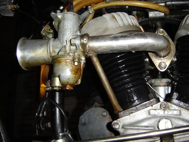
I was watching my copy of the BMW DVD "The Ride is On". While going through the history of BMW and its racing traditions, they mentioned the Type 255 Kompressor and showed a picture of it. I was struck by the presence of what appeared to be cooling fins on the intake portion of the head. Is that because of the compressor and potential heat that may have been left in the intake charge? It seemed that having these fins on the trailing side of the heads would do little to cool the intake to the engine.
I tried to do a screen shot of the part of the DVD but when I displayed it, it was blank. I had to resort to taking a digital picture of my screen and using that to display it. If I can do this right, here's a picture of what I saw. I tried to find any other photos from the archives but couldn't find anything from this angle.
If anyone has any thoughts or knowledge about this, I'd appreciate hearing about it.
Kurt in S.A.
Dedicated to the Preservation of Classic and Antique BMW Motorcycles.