(Archived from Peter Ardren’s vintagebmwbikeservice.co.uk site)
O.K. In part 2, I showed the various causes of differential (split) timing. Now that you’ve worked out what the cause is we can get rid of it.
I’m going to start at the inboard, camshaft, end and work outwards. That’s dealing with the least likely causes first, but there’s a sort of weird logic to my method that you’ll find later.
Let’s assume that there’s no problem with the camshaft itself. If it is, in fact, distorted or bent then you need a new one pronto. You shouldn’t even begin to consider using it.
Much more likely is the possibility that the male camshaft taper and female rotor shaft taper are not mating properly. If the one doesn’t sit exactly squarely with the other then there WILL be run-out and there WILL be differential timing.
The two tapers need lapping in together with fine carborundum (valve grinding) paste. The process involves smearing the end of the camshaft with a LIGHT coating and then rotating the rotor to grind both surfaces equally. An exactly even-coloured surface on both the rotor shaft and the camshaft tapers indicates when the process is complete. A good clean up, a check with the dial gauge that there’s no run-out and the job’s a good un.
But wait! How are you going to clean the excess off the camshaft taper? You can’t properly get a cloth in there because of the camshaft oil seal. Even if you sacrifice the seal by removing it you still can’t get much more access. Unless the taper is spotlessly clean then you will be introducing an abrasive compound into the engine internals. Instead of just having differential timing you are lining yourself up for some much more expensive repair work in the future. Quite simply you can’t do it this way! Don’t even think of trying it!!
The best way of lapping the rotor shaft and cam tapers is with the camshaft out of the engine. On all the engines I rebuild I now, as a matter of course, set the camshaft up in the lathe and make a really thorough job of lapping it in. A dial gauge then confirms that there’s no run-out and I know the rebuild will be comparatively easy. The trouble is that the camshaft shouldn’t be removed from the engine block without a lot of heat to free up the rear bearing. This means taking the flywheel off, and, preferably, removing the engine from the frame. It’s the proper way to do it but let’s face it, most people will try, at least initially, to cut corners and do a good job with the camshaft in situ and the engine still in the frame. Here’s what I suggest……..
1. Turn the crankshaft until the S mark is visible in the timing window. I’ll explain why later.
2. Remove the generator stator (label the wires so you know where to replace them).
3. Remove the generator rotor, using an extractor bolt. Salis stocks these or I can supply one.
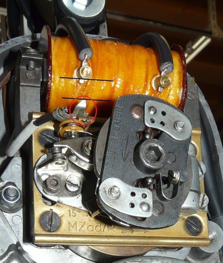
4. If the magneto is still in place then remove this too. The engine should be free of everything now and in the naked state you see it in the picture above.
5. Remove all the Allen key bolts holding the timing gear cover on.
6. You will need an extractor to remove the cover. Don’t even begin to think about levering it off – you’ll just damage mating faces. If you haven’t got an extractor then I can loan you one. Heat the area around thecrankshaft bearing to aid removal and avoid damage to the bearing housing.
7. With the cover off, the mysteries of the timing gears will be revealed. They will look like this:

Depending on your model and year the breather plate you can see on the camshaft may or may not be secured. If it will pull off easily then remove it.
Lapping in is straightforward. But remember I suggested you have the S mark in the timing hole?… Here’s my reasoning. On a lathe it’s easy to make sure the two pieces are fully rotating 360 degrees and you’re getting a complete and even lapping process. Being realistic, when you do it by hand with the camshaft still in the crankcase, you’re not going to be as even. You’re more likely to move the rotor about 90 degrees with the to and fro movement of your hand. So, if you start off with the rotor timing mark at the top, just as it will be when the magneto is all set up again, then you’re lapping the camshaft and rotor in roughly the correct position to each other. I don’t know if that makes sense to you – or whether my logic is skewed here – but it’s what I’ve always done and it works.
Finally, clean up both tapers, lightly bolt the rotor in position and use a dial gauge to check there’s no run-out.
Don’t forget to use a new gasket when you replace the timing cover – and to use heat around the bearing carrier to enable it to go on easier. I’d strongly advise you to fit two new oil seals into the cover before you re-fit it. They’ve done their job and don’t cost much to replace so best to renew them now rather than run the risk of an oil leak into the electrics. You can get the seals anywhere. You need a 25 x 35 x 7mm and a 28 x 40 x 7mm. You should really use a pusher to refit the timing cover but so long as the bearing carrier is hot enough then it will slide on without problem.
In part 4 I’ll show you how to deal with problems caused by a bent rotor shaft and ATU problems.